DC Motor Control with PWM

DC (Direct
current) motors frequently use in motion control systems. These can be run your
robots, give you relief in summer session as fan and etc. If you are going to
motion control field and you did not learned about motors control, you cannot
do anything.
In this
chapter we will discuss about controlling a small DC motor with PWM(see my post on PWM for briefly detail). Hardware designing
for motors is a pestilential task to selection the components, find accurate
motor parameters value like as current, heating, torque, etc. We need to test the circuit many of times.
Hardware Circuit
We are using
L298 H-bridge driver IC to bidirectional DC motor control. L298 have duel
bridge circuit and can be go up to 2 amperes current load each and accept TTL
logic (Can connect directly with microcontroller) supply input in order to
control the bridge circuit.

We will
connect bridges parallel to get higher current output. See L298 datasheet “Figure-7” and read all of related
information (Recommended) is given blow of figure (In datasheet) before make circuit.
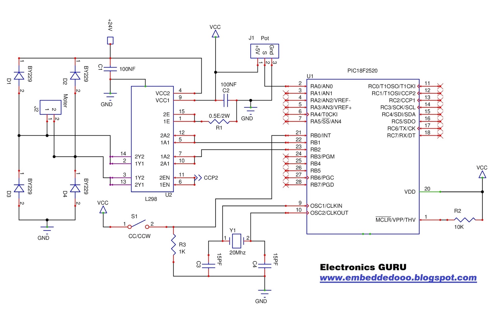
In the
schematic R1 resistance is current sensing resistance to sense the L298
output current. We can set output current limit by going on with practical and
find the right value of resistance. R1 resistance watts would be calculated
according to your motor load. You can change motor direction by S1 SPST switch.
CCP2 (PWM
mode) module is using for controlling motor speed according to PORTA-0 pin
analog input voltage. You can vary motor speed (0-100%) proportional to analog
input (0-5v).
Refer to my
previous articles for detailed description:-

Codes
#include <p18f2520.h>
#define Rvrs_Input PORTBbits.RB0 // Forward/Reverse
input
#define Forward PORTBbits.RB2
#define Reverse PORTBbits.RB1
void ADC_result(void);
void config_timer2(void);
void config_PWM_ccp2(void);
float ADC_data;
void main()
{
TRISA=0xFF; //
PORTA as Input
TRISB=0x01; //
PORTB-0 as Input abd other pins as Output
PORTB=0x00;
TRISC=0x00; //
PORTC as Output
PORTC=0x00;
ADCON0
= 0x01; //
ADC on, Channel-0 select.
ADCON1
= 0x0E; //
Volt reference VDD to Vss, AN-0 as analog input.
ADCON2
= 0xAE; //
Right justified, 12 TAD, FOSC/64.
config_PWM_ccp2();
config_timer2();
while(1)
{
ADC_result();
if(Rvrs_Input==1)
{
Reverse=1;
Forward=0;
}
if(Rvrs_Input==0)
{
Reverse=0;
Forward=1;
}
CCPR2L
= ADC_data * 45; // Set
ADC_data as per PR2 range.
}
}
void ADC_result()
{
ADCON0bits.GO
= 1; //
Set ADC conversion in progress.
while(
ADCON0bits.GO == 1 ); // Wait until conversion is not complete.
ADC_data
= (ADRESL + (ADRESH * 256)) / 204.8; // Convert AD value to voltage.
}
void config_timer2()
{
// Timer2 Registers:
// Prescaler=1:1; TMR2 PostScaler=1:11; PR2=227 - Freq =
2,002.40288Hz - Period = 0.4994 ms
T2CONbits.T2OUTPS3
= 1; //
Postscaler selection bits
T2CONbits.T2OUTPS2
= 0;
T2CONbits.T2OUTPS1
= 1;
T2CONbits.T2OUTPS0
= 0;
T2CONbits.TMR2ON = 1; // Timer2
on bit: 1=Timer2 is on;
T2CONbits.T2CKPS1
= 0; // bits 1-0
Prescaler Rate Select bits
T2CONbits.T2CKPS0
= 0;
PR2
= 227; // PR2 (Timer2 Match value)
}
void config_PWM_ccp2()
{
CCPR2L=0; //
Set duty cycle register value to 0.
CCP2CONbits.CCP2M3
= 1; //Selecting
PWM mode
CCP2CONbits.CCP2M2
= 1;
CCP2CONbits.CCP2M1
= 0;
CCP2CONbits.CCP2M0
= 0;
}
Download Project file :- https://drive.google.com/file/d/0B886Kbl42IVuTDZqdGQtbFVnSEU/view?usp=sharing


No comments:
Post a Comment